
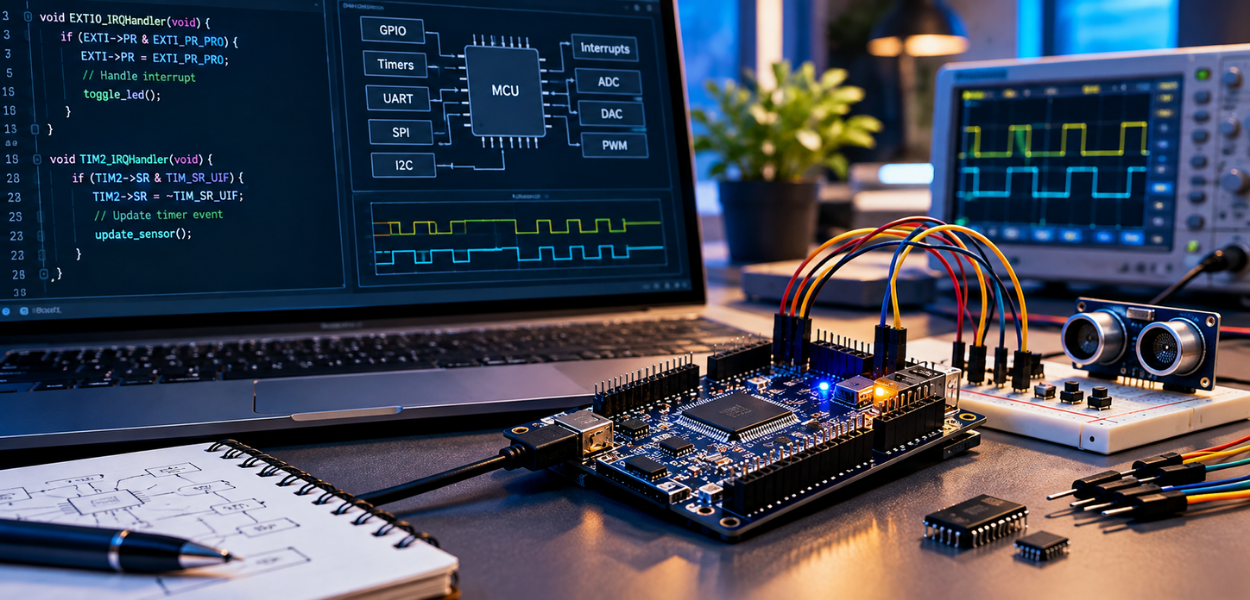
Embedded systems engineers spend most of their working hours managing three mechanisms: interrupts, timers and peripheral drivers. These three elements determine whether a device responds correctly under real-world conditions or fails when timing margins narrow. Organisations building firmware teams need engineers who understand these mechanisms at a hardware level, not just at a syntax level.
Interrupt handling, timer configuration and peripheral driver design form the operational core of microcontroller programming. A microcontroller without correctly configured interrupts cannot respond to sensor events, communication packets or safety triggers within acceptable time windows. Teams evaluating training options for their engineers typically start by reviewing structured Embedded Systems and Microcontroller Programming Training Courses, which cover these fundamentals before engineers move into applied firmware projects. This sequencing matters because interrupt and timer concepts build directly on register-level programming knowledge introduced at that stage.
What Are Interrupts and Why Do They Matter in Microcontroller Programming?
Interrupts are hardware or software signals that pause the main program to execute a higher-priority task immediately, then return control once that task completes. They allow a microcontroller to react to external events without continuously polling every input pin. This distinction separates efficient embedded firmware from firmware that wastes processor cycles checking conditions that rarely change.
A microcontroller running without interrupts must poll each peripheral in sequence. Polling wastes CPU cycles and introduces latency proportional to the polling loop length. A system polling ten peripherals every millisecond may miss a fast sensor event lasting only 200 microseconds. Interrupts eliminate this gap by triggering an interrupt service routine (ISR) the moment a condition occurs, regardless of what the main loop is doing.
ARM Cortex-M processors, widely used in industrial and consumer embedded products, support up to 240 external interrupt lines depending on the microcontroller variant. Each interrupt carries a priority level, configurable through the Nested Vectored Interrupt Controller (NVIC). Engineers configure priority levels to ensure safety-critical interrupts, such as an over-current trigger, always pre-empt lower-priority interrupts, such as a UART receive buffer update.
Interrupt latency, the time between a trigger event and ISR execution, typically ranges from 12 to 20 clock cycles on ARM Cortex-M4 devices running at 100 MHz. This equates to roughly 120–200 nanoseconds. Firmware teams measure this figure directly because it defines the theoretical minimum response time for any safety or control loop built on that hardware.
How Do Timers Control Real-Time Behaviour in Embedded Systems?
Timers are hardware peripherals that count clock cycles to measure elapsed time, generate periodic events or produce precise output signals without continuous CPU involvement. They convert a fixed clock frequency into usable time intervals for tasks ranging from motor control to communication protocol timing.
A microcontroller timer operates independently of the main program once configured. It counts up or down from a preset value and triggers an interrupt or hardware action when it reaches a threshold. This frees the processor from manually tracking elapsed time through counting loops, which are inaccurate and consume processing capacity.
Three timer functions appear consistently across embedded projects. Input capture measures the duration or frequency of an external signal, used in applications such as measuring motor RPM. Output compare generates a signal transition at a defined time, used for driving stepper motors or generating precise delays. Pulse-width modulation (PWM) varies the duty cycle of an output signal, used for motor speed control, LED dimming and power regulation.
Timer resolution depends on clock frequency and prescaler configuration. A timer running from an 80 MHz clock with no prescaler achieves 12.5-nanosecond resolution. Applying a prescaler of 80 reduces resolution to 1 microsecond while extending the maximum measurable interval. Engineers select prescaler values based on the required balance between precision and range, a calculation performed for every timer-dependent feature in a project.
Real-time operating systems (RTOS) rely on a dedicated system timer, often called SysTick on ARM Cortex-M devices, to manage task scheduling. This timer generates an interrupt at a fixed interval, commonly every 1 millisecond, allowing the RTOS scheduler to evaluate which task should run next. Without accurate timer configuration, task scheduling drifts, and time-sensitive operations such as sensor sampling lose synchronisation.
How Does ARM Cortex Interrupt Prioritisation Affect System Design?
ARM Cortex processors use a Nested Vectored Interrupt Controller to assign priority levels to each interrupt source, determining execution order when multiple interrupts occur simultaneously. This prioritisation prevents low-importance events from delaying safety-critical responses.
Cortex-M devices support priority grouping, splitting priority values into preemption priority and sub-priority. Preemption priority determines whether an active ISR can be interrupted by a new event. Sub-priority determines execution order among interrupts of equal preemption priority that arrive at the same time. Engineers configure priority grouping through the NVIC registers, a task requiring direct knowledge of the processor's programming manual rather than reliance on default settings.
Interrupt nesting introduces stack usage considerations. Each nested interrupt consumes stack space for saved registers. A design permitting four levels of nesting on a device with 2 KB of stack allocated must verify that worst-case nesting does not exceed available memory. Stack overflow from excessive nesting causes unpredictable behaviour, one of the more difficult firmware faults to diagnose because it appears intermittently under specific timing conditions.
What Role Do GPIO Configuration and Peripheral Drivers Play in Firmware Reliability?
GPIO configuration and peripheral drivers translate abstract firmware logic into electrical signals, and incorrect configuration at this layer produces failures that appear only under specific voltage, timing or load conditions. This layer sits directly above the hardware and directly below application logic.
General-purpose input/output (GPIO) pins require configuration across several parameters before use: direction (input or output), pull-up or pull-down resistor state, output drive strength and alternate function mapping. A single GPIO pin on a modern microcontroller often supports six or more alternate functions, such as UART, SPI, I2C or timer output. Selecting the wrong alternate function silently disables the intended peripheral without producing a compile error, which makes this a common source of firmware debugging time.
Peripheral drivers manage communication protocols including SPI, I2C, UART and CAN. Each protocol has distinct timing requirements. I2C, for example, operates at standard speed (100 kHz), fast mode (400 kHz) or fast mode plus (1 MHz), and driver code must configure clock stretching and acknowledgement handling correctly for the target speed. SPI drivers must match clock polarity and phase settings between master and slave devices, since a mismatch produces corrupted data transfer despite correct wiring.
Firmware development teams typically build a hardware abstraction layer (HAL) above raw register access. This layer standardises peripheral driver calls across microcontroller families, reducing rework when a product moves from one chip variant to another. Engineers who understand register-level operation can debug HAL-layer issues that abstraction alone cannot resolve, a skill gap organisations frequently identify during firmware project reviews.
How Do Real-Time Operating Systems Change Interrupt and Timer Management?
Real-time operating systems introduce task scheduling, priority inheritance and inter-task communication, requiring engineers to manage interrupts and timers within a multitasking framework rather than a single linear program. This shifts firmware design from sequential logic to concurrent task management.
Bare-metal firmware executes interrupts and timers within a single continuous loop. An RTOS instead divides functionality into tasks, each with an assigned priority, and the scheduler determines execution order based on timer-driven context switching. Interrupt service routines in an RTOS environment must remain short, typically deferring processing to a task through a semaphore or message queue rather than performing lengthy operations inside the ISR itself.
Priority inversion is a documented RTOS risk, occurring when a low-priority task holds a resource needed by a high-priority task, while a medium-priority task blocks the low-priority task from running. Priority inheritance protocols, built into RTOS kernels such as FreeRTOS and Zephyr, temporarily raise the low-priority task's priority to resolve this. Engineers configuring RTOS-based firmware must understand this mechanism, since unresolved priority inversion has caused documented failures in safety-critical systems.
Task scheduling overhead also affects timer accuracy. Each context switch consumes processor cycles, typically between 100 and 500 cycles depending on the number of registers saved. On a system running many tasks at high frequency, this overhead accumulates and reduces the processing time available for actual application logic, a factor engineers must account for during system sizing.
What Skills Do Employers Verify When Hiring Embedded Systems Engineers?
Employers assess candidates on register-level interrupt configuration, timer calculation, peripheral driver debugging and RTOS task design, since these skills determine whether a candidate can diagnose and resolve real firmware faults rather than only write code that compiles. Technical interviews for embedded roles routinely include live debugging exercises rather than theoretical questions alone.
Workforce skill gaps in this area are well documented across engineering hiring processes. Candidates frequently demonstrate familiarity with high-level programming languages but struggle when asked to explain interrupt latency, calculate timer prescaler values or identify a GPIO misconfiguration from a schematic. This gap directly affects project timelines, since firmware faults traced to these fundamentals extend debugging phases beyond initial estimates.
Organisations addressing this gap structure training around practical application rather than theory alone, measuring competency through hands-on exercises involving oscilloscope verification, logic analyser interpretation and live register configuration. Engineers who complete training that includes this applied component demonstrate measurably faster fault diagnosis in subsequent project work, since they have already practised connecting symptom to root cause under supervised conditions.
For engineers preparing to demonstrate these exact competencies under interview conditions, the practical route is to Build Embedded Systems and Microcontroller Skills That Employers Verify at Interview, a programme structured around the interrupt, timer and peripheral driver scenarios interviewers use to assess technical readiness. This path suits engineers who have completed foundational training and now need verified, interview-ready proficiency rather than further conceptual coverage.
Embedded systems training sits within a broader technical skills framework. Organisations building firmware capability alongside other technical disciplines often structure this development through the wider Information Technology and Programming Courses, ensuring embedded engineers develop alongside software and systems teams working on adjacent parts of the same products.
Explore More Expert Insights:
Spectrum Management: ITU Radio Regulations and National Frequency Allocation Explained
Satellite Communication Systems: Orbits, Transponders and Footprint Coverage Explained
Firmware reliability depends on engineers who treat interrupts, timers and peripheral drivers as measurable, testable components rather than background configuration. Organisations that invest in this depth of training reduce field failures, shorten debugging cycles and produce engineers capable of defending their design decisions under technical scrutiny, whether from a project review board or an interview panel.